

Where did you guys mount your comm and transponder antenna's? I leanred one thing, mount your antenna "mounts" before you do your fabric. I'm setting my ELT antenna and I'm working up through the access door. Would have been reall easy before the fabric was on. For the comm., I'm thinking on top of the window like Lynn's and for the thransponder, maybe right below the pedals? on one of the front wheel mounts I won't be using.??
Paul, PA
Antenna mounting
-
b1x4nqb
- Veteran Member
- Posts: 282
- Joined: Mon Aug 14, 2006 11:53 am
- Location: Orwigsburg, PA
-
scubarider2

- Topic Moderator
- Posts: 1086
- Joined: Mon Jan 28, 2008 7:03 pm
- Location: Cleveland, GA
turtle deck
I mounted my comm antenna on the back center of the turtle deck. Works great and is out of the way.
My ELT antenna on the inside right on the bracket I made up.
Dennis
My ELT antenna on the inside right on the bracket I made up.
Dennis
-
Wes
- Premium Member
- Posts: 231
- Joined: Mon Jan 23, 2006 10:32 pm
- Location: Satellite Bch, Florida
Antenna Mounts
Paul,
Some tips from an "avionics guy" (me),
- try to get your transponder antenna in the clear as much as possible. Gear legs will shade the antenna and you will 'drop out' on ATC radar when it you need it most. If you combine the shortest coax run possible (to minimize power loss) with a clear area on the Highlander, that puts your antenna somewhere aft of the main gear legs and forward of the seat backs. Be sure to have at least a 6 inch diameter ground plane around the stub antenna and use the min. loss coax, RG142 or RG-304 or any double shielded qualty coax that will give you less than 1.5 dB loss for the run, (Including connector losses). No RG58 stuff.
- Com antenna can be anywhere on top, but should have a good ground plane. It's tuff to get the 22 inches of ground plane all around the antenna (radius from the whip), but do the best you can. I'm planning using the turltle deck ( like Dennis's) because it's the biggest piece of aluminum up there. Just have to plan a disconnect at the base of the whip for deck removal (not a bad compromise for the gain in antenna performance). Use a good quality coax, RG-400 or similar and keep the run as short as possible.
- The ELT (for whatever good they are) antenna should be on top also and same com advice applies. Antennas tucked inside the steel tube fuselage with little ground plane are not going to be very effective, but then again the whole VHF ELT system (search and rescue) is pretty IFFY. I'm putting my money in a 406MHZ hand held locator, - not FAA legal, but much more effective. I'll probably buy a used, semi-functional VHF ELT just to satisfy the feds.
Hope this helps,
Wes
kit #95
Kit # 95
Low and Slow - The only way to go!
Low and Slow - The only way to go!
-
b1x4nqb
- Veteran Member
- Posts: 282
- Joined: Mon Aug 14, 2006 11:53 am
- Location: Orwigsburg, PA
Wes,
Thanks for the tips! When you refer to the "ground plane" I assume you mean I need something actually attached to the airframe via either welded or at least the powder coat removed to get a good ground to the frame?? You mentioned the turtle deck and that really doesn't have a lot of contact but I saw a double meaning and wanted to clarify.
Thanks,
Paul, PA
-
KevinC
- Veteran Member
- Posts: 447
- Joined: Fri Aug 19, 2005 12:42 am
- Location: Prosser, Washington
Comm question for Wes
Wes,
I was planning to mount my comm antenna in the right rear corner of the overhead plexi - on an aluminum plate. I saw this on two of the factory birds, and they both said it worked well.
dumb idea?
k

I was planning to mount my comm antenna in the right rear corner of the overhead plexi - on an aluminum plate. I saw this on two of the factory birds, and they both said it worked well.
dumb idea?
k
-
Wes
- Premium Member
- Posts: 231
- Joined: Mon Jan 23, 2006 10:32 pm
- Location: Satellite Bch, Florida
Antenna Mounts
Paul,
That's right, the antenna 'ground plane' or couterpoise can be independant of the structure (not electrically connected).
If there is insufficient ground plane surface (it doesn't have to be absolutely continuous, - mine will have a window in it) the feed point will not be a good impedance match for the 50 ohm coax and that leads to all sorts of nasties like tx power radiating from the coax run and disrupting sensitve instruments and distorting audio, etc.
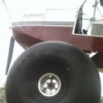
Here's a pic of the two ground planes I put on the bottom of my Highlander. One is for ham UHF and the other is for transponder.
Wes
Kit #95
That's right, the antenna 'ground plane' or couterpoise can be independant of the structure (not electrically connected).
If there is insufficient ground plane surface (it doesn't have to be absolutely continuous, - mine will have a window in it) the feed point will not be a good impedance match for the 50 ohm coax and that leads to all sorts of nasties like tx power radiating from the coax run and disrupting sensitve instruments and distorting audio, etc.
Here's a pic of the two ground planes I put on the bottom of my Highlander. One is for ham UHF and the other is for transponder.
Wes
Kit #95
You do not have the required permissions to view the files attached to this post.
Kit # 95
Low and Slow - The only way to go!
Low and Slow - The only way to go!
-
Wes
- Premium Member
- Posts: 231
- Joined: Mon Jan 23, 2006 10:32 pm
- Location: Satellite Bch, Florida
Com Antenna mounts
Kevin,
Yeh I saw those mountings on a lot of Just birds and I sort of cringe (being an opinionated avionics type).
I had actually considered doing that for mine, but rejected it for 2 reasons; -structurally weak area, - terrible place to try to construct a proper ground plane.
Do they work?, well sort of. But I can guess that the coax is going to radiate like gang busters and that is going to lead to all kinds of wierd electronics behavior every time you transmit.
If that is the best place for an antenna in your project, I would give the antenna the best chance of a proper match by adding 22 inch aluminum (or copper) radials extending out from the base and electrically connected to the coax shield or antenna ground. These radials would approximate a counterpoise sheet of 1/4 wavelength. As a minimum it would be good to electrically tie the antenna ground to that aluminum trim piece that extends across the cockpit (with the EXPERIMENTAL on it).
You could also extend a radial along the inside of the butt rib. Anything would help, and the more the merrier.
Wes
Kit #95
Kit # 95
Low and Slow - The only way to go!
Low and Slow - The only way to go!
-
rgmullins
- Veteran Member
- Posts: 103
- Joined: Tue Sep 04, 2007 8:21 am
- Location: Cincinnati
Perfect timing on this thread. I was installing my radio and transponder this last weekend.
Wes do you think it would be possible to put a transponder plane in the bottom where your is after it's already been covered? Seems like you could fit it, then just glue it in place to the fabric.
I don't think I've ever seen orange fabric glue before....
Wes do you think it would be possible to put a transponder plane in the bottom where your is after it's already been covered? Seems like you could fit it, then just glue it in place to the fabric.
I don't think I've ever seen orange fabric glue before....
Rick Mullins #144
Cincinnati
Cincinnati
-
Wes
- Premium Member
- Posts: 231
- Joined: Mon Jan 23, 2006 10:32 pm
- Location: Satellite Bch, Florida
Transponder Stub Mount
Rick,
I was anticipating that situation and don't see a problem with just glueing it in.
Here's some suggeations:
- use thinnest sheet available (maybe .016 or .020 6061) to make a nice big plate to fit the area to be glued in (at least 12 X 12 in)
- make a round 'doubler' out of .020 or .032 about 6 in in diam. and flush rivet to the big plate to position the antenna toward the bottom stringer. This doubler would end up on the non-fabric side of the assy.
- bore the mount hole for the stub antenna in the middle of the round piece.
- mask off a circle about 1 in diam around the mount hole (on the inside for grounding the antenna mount) and epoxy primer the the whole assy. This may be an optional step, but in Florida, EVERYTHING has to be painted or kiss it goodby after a year in the salt air.
Then just glue the whole thing in position and after set up, melt your whole for the stub.
I think this setup would have plenty of support from the fabric, especially with the small stub antenna.
Oh, and the 'orange' fabric is the Polyfiber polybrush fabric sealer. Lovely color don't you think!
Wes
Kit # 95
Low and Slow - The only way to go!
Low and Slow - The only way to go!
-
scubarider2
- Topic Moderator
- Posts: 1086
- Joined: Mon Jan 28, 2008 7:03 pm
- Location: Cleveland, GA
my antenna
Here is a picture of my antenna mounted on the turtle deck. Quick release connector for easy removal.
Dennis
Dennis
You do not have the required permissions to view the files attached to this post.
-
rgmullins
- Veteran Member
- Posts: 103
- Joined: Tue Sep 04, 2007 8:21 am
- Location: Cincinnati
-
Wes
- Premium Member
- Posts: 231
- Joined: Mon Jan 23, 2006 10:32 pm
- Location: Satellite Bch, Florida
Transponder Antenna Mount
Rick,
I just went out and measured my cable run for the transponder and it is about 6 1/2 ft from the transponder down to the antenna. That is with the antenna about 8 in aft. of the main gear leg on the Highlander. It is another 10 FT. from there back to the service panel at the tail, so the total run to the tail would be about 16 FT. ! That's way too much coax cable to be using on a transponder install. Your losses with even the best coax would far exceed the recommended 1.5 dB max. loss figure. You could pretty much be gauranteed a marginal performing system.
So, I do not reccommend that location.
I am so paranoid about transponder signal losses, that I bought some Andrews 1/2 inch hard line coax at the Orlando Hamfest (cheap) and I will build my transponder coax run from it. Even with connector losses, I should end up with about 0.7 dB total loss for the 6 1/2 ft. run. A little over-kill there, but I do a lot of flying around the Orlando class B airspace and I hate not showing up on their radar.
If you need some help figuring losses for the coax, let me know the cable type and distance and I can work it for you.
Just back from a week at Sun-N-Fun and now broke.
Hope this helps.
Wes
Kit #95
Kit # 95
Low and Slow - The only way to go!
Low and Slow - The only way to go!
-
Dave Krall CFII SEL SES
- Veteran Member
- Posts: 922
- Joined: Wed Mar 14, 2007 11:29 pm
- Location: Seattle WA
-
b1x4nqb
- Veteran Member
- Posts: 282
- Joined: Mon Aug 14, 2006 11:53 am
- Location: Orwigsburg, PA
"I'm planning using the turltle deck ( like Dennis's) because it's the biggest piece of aluminum up there. Just have to plan a disconnect at the base of the whip for deck removal (not a bad compromise for the gain in antenna performance)."
Wes/Others,
My antenna has a weather shield that appears to totally isolate the metal turtle deck from the antenna base. How does the "ground plane" work in this case? My antenna is similar to Dennis's but has 4 mounting holes instead of three, made by Comant. Just a BNC on the bottom, no grounding screw or anything else. Is that it or do I need to run a grounding strap somehow?
Thanks,
Paul, PA
-
Wes
- Premium Member
- Posts: 231
- Joined: Mon Jan 23, 2006 10:32 pm
- Location: Satellite Bch, Florida
VHF Antenna Grounding
Paul,
The comercial VHF antennas are designed primarily for aluminum skinned airplanes and must have an electrical connection to the skin.
Having said that, the designs I have seen don't make it real easy to accomplish this grounding. I guess they assume you will have lots of bare aluminum to attach to.
The important thing to keep in mind is that the shell of the BNC and the associated metal parts of antenna must be in contact with the turtle deck. This is usually accomplished by some star washers on the attaching hardware. I recall that some of the countersunk screws had conical star washers supplied that insured a good connection between the metal base and the fastener. Then it was your job to insure the fastener was well grounded to the skin.
I know of no aircraft VHF whips that are "stand alone", that is, they all require a ground connection, unlike some ham antennas that have matching elements in the base that make a ground connection optional.
The original aircraft VHF whips were just that, a straight (or bent) 1/4 wave antenna made from a tapered SS rod with a porcelin insulator to mount it thru the skin with the coax shield grounded to the aluminum at that point. These worked fairly well with a reasonable VSWR (measure of impedance match) over the limited com freqs of the day (118 to 128 mhz). As the band was expanded to 135 mhz, the whips performed pretty poorly when asked to resonate at the higher freqs, so commercial antennas were redesigned with matching sections in the base to present a better match over the broader freq. range. That's the antenna you have today.
I have always built my own antennas, mostly straight 1/4 wave whips and just 'take the hit' if I need to talk on freqs above about 128 mhz. Generally I can still be heard, but their reciever is doing all the work, not my transmitter. I'm working on a reliable matching section to broaden the coverage of my whip. We'll see.
Just remember to finish your installation with a healthy bead of silcone seal all around the base and over the mounting screws to seal moisture out of the interface between the antenna base and the deck.
Kit # 95
Low and Slow - The only way to go!
Low and Slow - The only way to go!